Installing traffic spikes can be a hassle when you're not sure what you're doing, especially since it can differ depending on brand to brand or largely, if it's surface mount or flush mount. We've gone ahead and collected a few printable manuals, diagrams, as well as wrote out the steps you need to properly and safely install your Delta Scientific Surface Mount & In-Ground Traffic Spikes. Let's take a look!
General Installation Notes for Delta Scientific Traffic Spikes
Before getting started, there's some general guidelines that you should go over to ensure that your traffic spikes are not only safe but effective:
- Spike Orientation: Spikes should always be placed with the points facing away from oncoming vehicles.
- Signage and Visibility: It's important to keep spikes visible and have clear signage to indicate their presence. Traffic spikes are meant for traffic control, not traps.
- Speed Control Recommendations: It's recommended that extremely low speed is used on traffic spikes, around 5 MPH to ensure tires don't spin too fast and hit a spike unnecessarily.
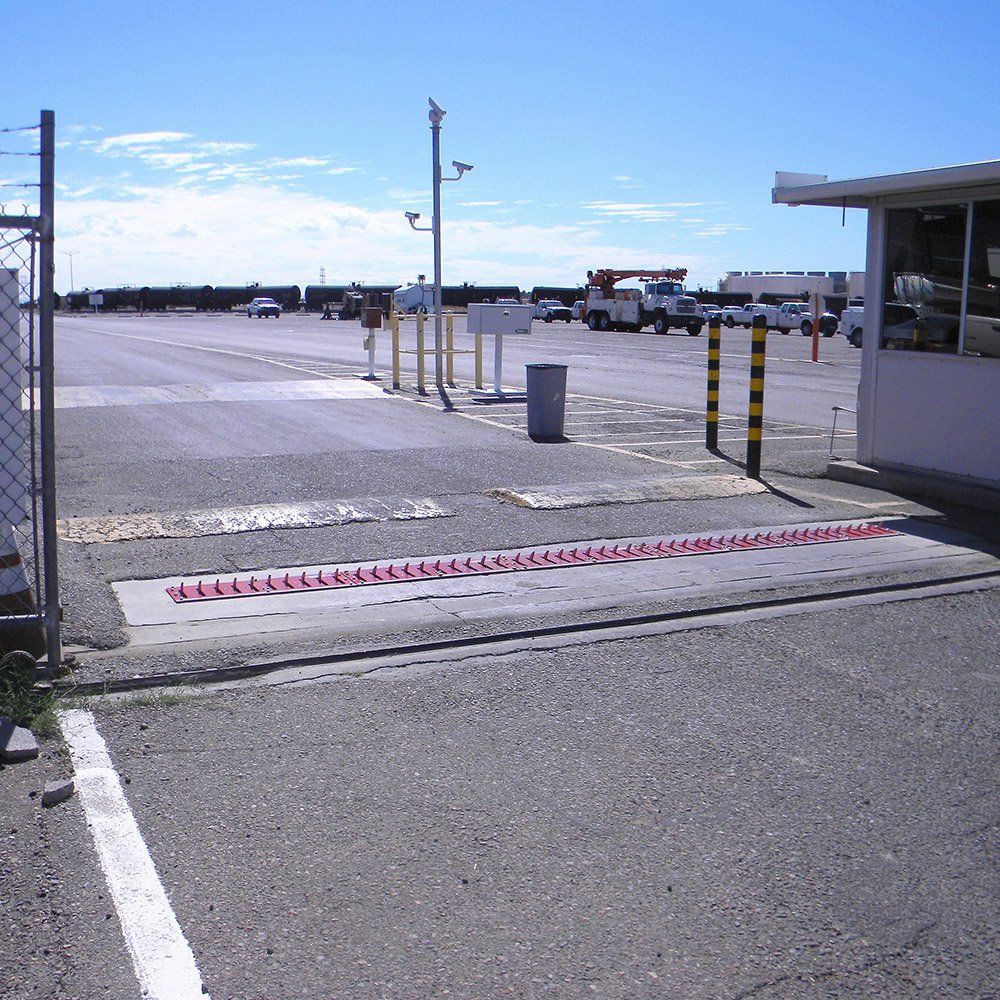
For best usage of your Delta Scientific Traffic Spikes, place your surface-mounted spike barriers:
- On flat surfaces, made of concrete or asphalt
- Where the max speed of travel is 5mph or less
- Away from public roads, so unintentional damage does not occur
- Away from pedestrian areas, or restrict pedestrians from the area
- 90° to the flow of traffic, so that unintended tire damage does not occur
Delta Scientific Surface Mount Traffic Spike Installation
Step One: Pre-Installation Notes
Once you're ready to begin installing take care to read through the following notes as they will inform you of the correct part and traffic spike orientation as well as other key things such as clearance and product labeling.
- Each of the three basic components are pre-drilled to allow bolting directly to the slab
- Before final disassembly, each component was steel stamped according to handing (right or left), position relative to the motor cabinet, and system number
- For example a unit stamped: "3R1" Indicates a right hand, first section of system number 3. The section should be laid out in the correct order on the site making sure the steel identity numbers match
- Each set of teeth and the drive shaft tunnels are stamped and must be in the indicated order (the higher the number, the further away from the drive box)
- Remove the top plates and lay aside. After you are sure of the order and location, move each component into place starting with the module most distant from the motor cabinet
- Be sure that the teeth and drive shafts are aligned and fully inserted
- There are overlapping tabs on each section, which once aligned should match the threaded holes on the next section. When aligned, there should be approximately 1/4" clearance between sections
Step Two: Mechanical & Electrical Components Installation
- Once the components are in place, and before lagging down or pinning the couplings, raise the teeth to the upright position and make a visual check of the alignment. Note: The teeth should all be in line, this can be checked with a string line
- Once aligned and checked, tighten the tie down bolts along the edge and the bolts on the inside tabs
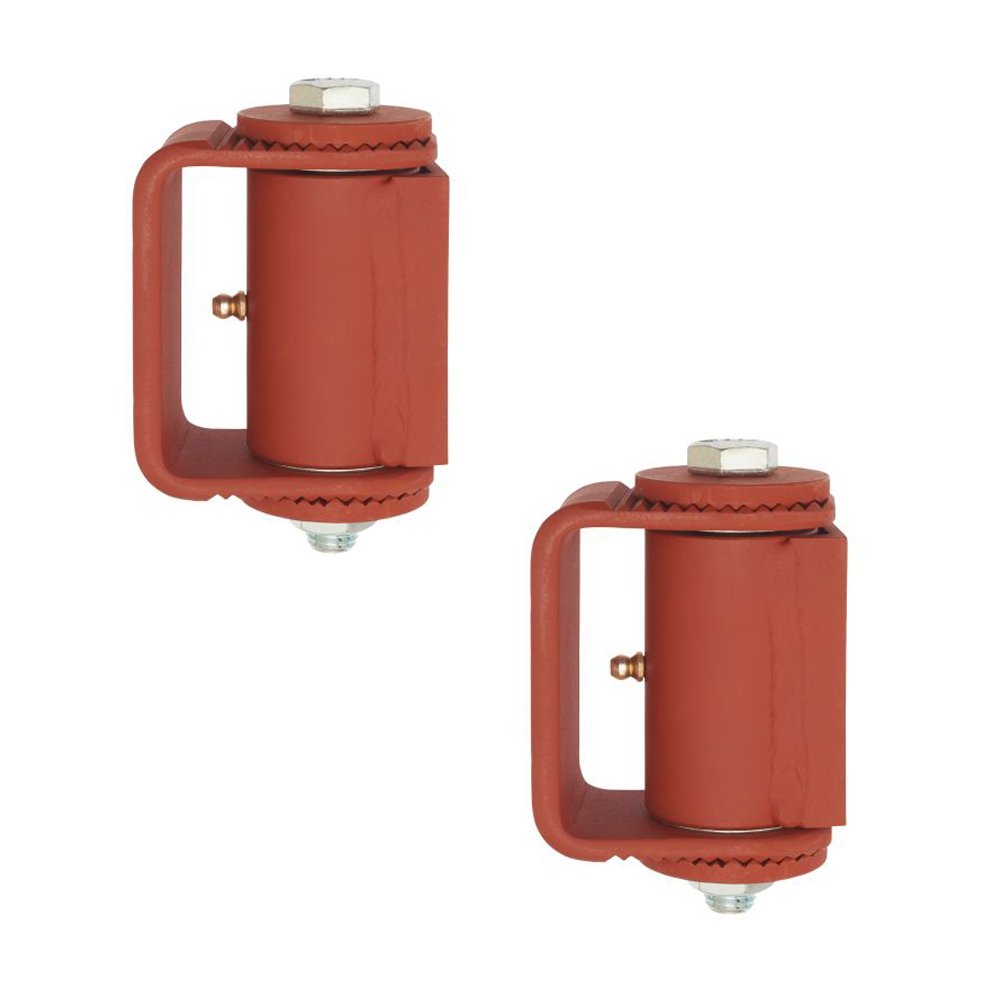
- Drive the coupling pins into the pre-drilled holes and lightly stake
- Attach the connecting link from the gearbox to the drive shaft crank arm
- Place the spacer between the connecting link and the crank arm
- Pull the high tensile strength bolt tight with the self-locking hex-nut (about 35-40 ft-lbs.)
- Tighten the set screw in the drive shaft collar adjacent to the crank arm
- Check belt tension (1/2" of slack maximum)
- The unit is now ready for electrical hook-up (See Printable Diagram for Wiring Configuration)
Important Notes for Electrical Setup
- Before operating under power, the motor should be run through the cycle by hand to make sure there are no interference or obvious problems
- After the crank through, the top plates can be bolted into place
- The direction of the slots must allow for free retraction of the teeth. No adjustment of the limit switch or connecting link should be necessary
Delta Scientific In-Ground Traffic Spike Installation
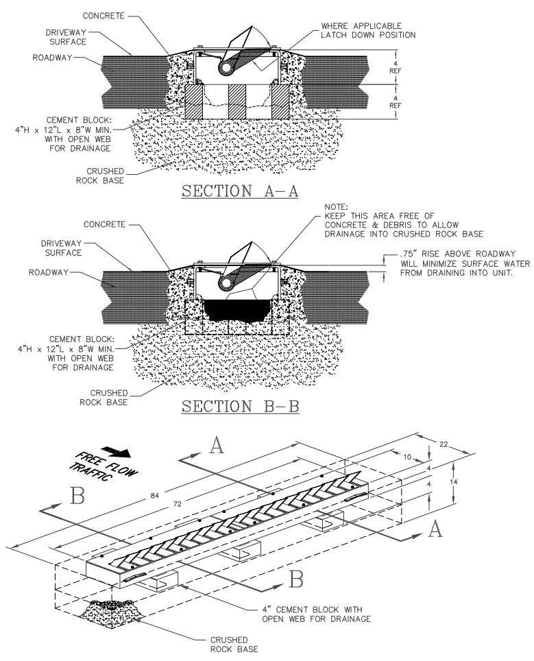
Printable Instructions Shop All Delta Scientific Traffic Spikes