Knowing how to install traffic spikes can be tricky especially when installation can look different depending on the brand of spikes you're using. Spike Systems, Delta Scientific, Road Blade, they all look a little different, especially between the different models each brand offers. Luckily, we've put together a few installation guides for you, with this guide including some general installation steps for Spike Systems' Surface Mount, In-Ground, and Motorized Traffic Spikes. Let's take a look!
General Installation Notes for Spike Systems Traffic Spikes
Before getting started, there's some general guidelines that you should go over to ensure that your traffic spikes are not only safe but effective:
- Spike Orientation: Spikes should always be placed with the points facing away from oncoming vehicles.
- Signage and Visibility: It's important to keep spikes visible and have clear signage to indicate their presence. Traffic spikes are meant for traffic control, not traps.
- Speed Control Recommendations: It's recommended that extremely low speed is used on traffic spikes, around 5 MPH to ensure tires don't spin too fast and hit a spike unnecessarily.
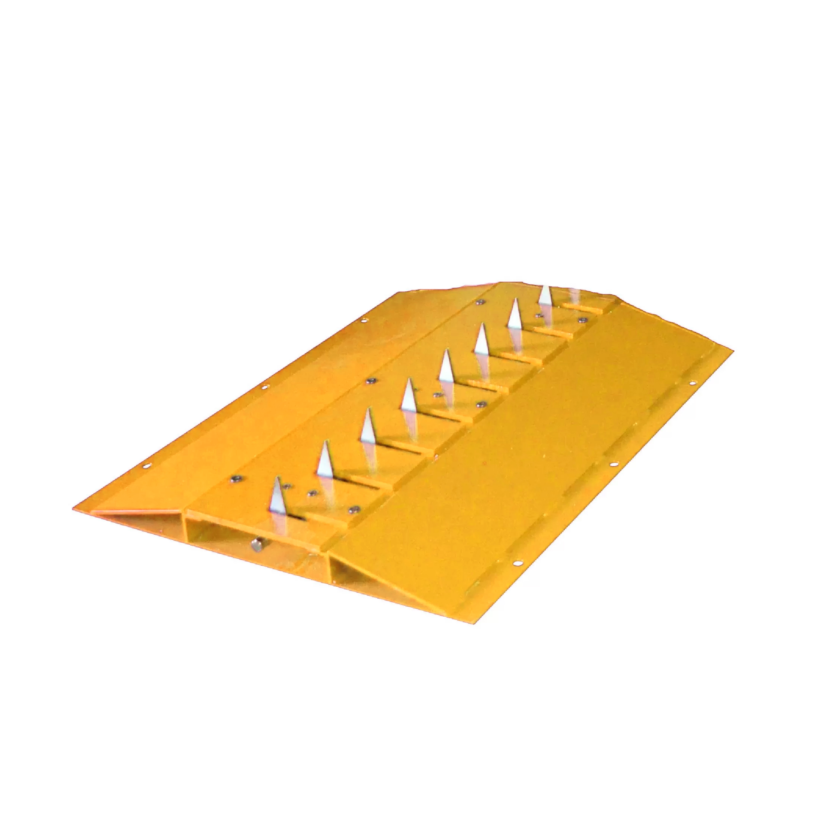
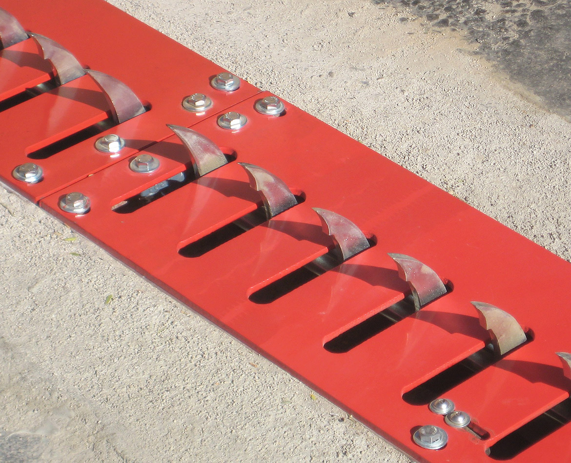
Spike Systems Surface Mount Traffic Spikes
Step One: Site selection & Placing Barriers
- Locate your Spike Systems installation hardware & prepare your installation surface by removing any debris
- Place the Spike Systems barriers into the exact location they will be permanently installed, placing all barrier modules directly beside each other with no gap
- Make sure the blades are facing the correct direction before installing
For best usage of your Spike Systems Traffic Spikes, place your surface-mounted spike barriers:
- On flat surfaces, made of concrete or asphalt
- Where the max speed of travel is 10mph or less
- Away from public roads, so unintentional damage does not occur
- Away from pedestrian areas, or restrict pedestrians from the area
- 90° to the flow of traffic, so that unintended tire damage does not occur
Step Two: Remove the Lock-down Bolts & Cover Plates
- Remove the center lock-down bolt from each unit with a 3/4” socket. Keep this bolt to lock down the blades later
- Remove the cover plate bolts and name plates using an impact drill with a 3/4" socket
- Remove the cover plate to expose the mounting holes.
Step Three: Drill pilot holes, install anchor bolts
- Using a 3/8” drill bit with a hammer drill (if available), or a standard drill, create pilot holes for the anchor bolts
- Using the mounting holes as a guide, drill to 4.25” depth
- After drilling all pilot holes, clear out any dust/debris that would obstruct installation hardware
- Using an impact drill with a 3/4” socket, install the anchor bolts.
Step Four: Secure cover plates, install accessories
- Once the cover plates are reinstalled, install beveled end caps if applicable
- Place signage and nighttime illumination to inform drivers about potential tire damage.
Printable Instructions
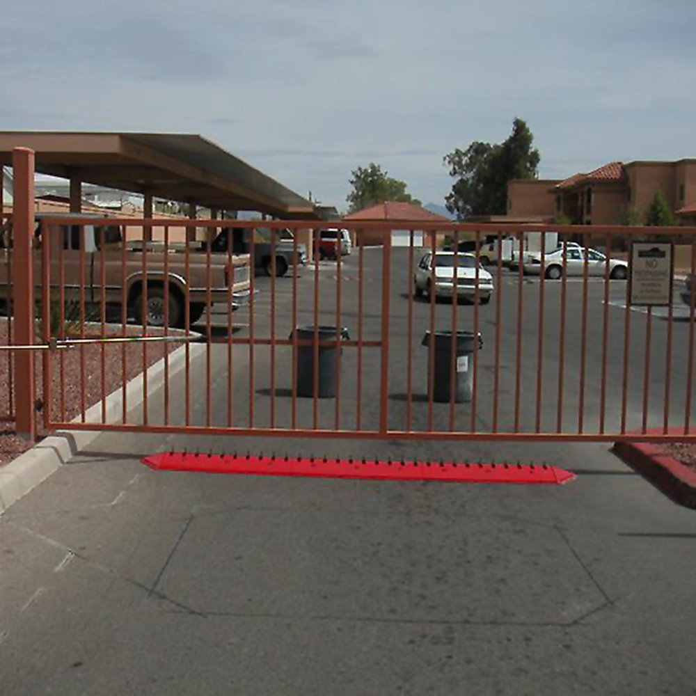
Spike Systems In-Ground Mount Traffic Spikes
Equipment needed to saw cut installation trench:
- Shovels
- (3) Three concrete blocks
- 12 to 16 bags of premix cement
- Allen wrench
- 3' straight edge
- Trowel to finish cement
- Bag of pea gravel
Step One: Site selection
- Locate your Spike Systems installation hardware & prepare your installation surface by removing any debris
- Place the Spike Systems barriers into the exact location they will be permanently installed, placing all barrier modules directly beside each other with no gap
- Make sure the blades are facing the correct direction before installing
If the vehicles will be crossing the CS36-FM in excess of 5 MPH, a speed bump and/or a Rumble Strip must be installed as well. For best usage of your Spike Systems Traffic Spikes, place your surface-mounted spike barriers:
- On flat surfaces, made of concrete or asphalt
- Where the max speed of travel is 10mph or less
- Away from public roads, so unintentional damage does not occur
- Away from pedestrian areas, or restrict pedestrians from the area
- 90° to the flow of traffic, so that unintended tire damage does not occur
Step Two: Saw Cut the Installation Hole
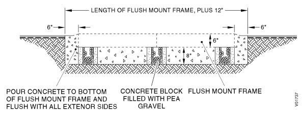
Saw Cut no less than the diagram shown below across, 36" wide, and 11"deep.
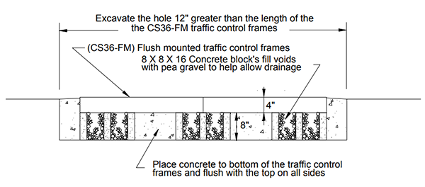
Step Three: Insert the Container Box and fill hole
- Remove the Top plate bolts from the CS36-FM and remove the 3 top plates and place them to the side
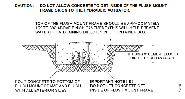
- Place and center the CS36-FM container box (frame) atop the two concrete blocks Tip: A straight edge will be useful to determine when the box is 1/2" to 3/4" above the finish grade of the asphalt (see diagram below)
- Fill the excavated trench with cement to the bottom of the CS36-FM container box and flush with the to the top on all sides
- Finish filling the hole around the outside of the container until the cement is even with the top of the container box and the top of the asphalt
- When the cement has begun to set up, fill the concrete block holes with pea gravel to prohibit debris form entering the hole
- Allow the concrete to cure, and then reinstall the top plates. If needed use a screwdriver to align the container box with the holes in the top plate if they do not align when reinstalling the top plates
- Locate the system away from pedestrian traffic and restrict pedestrian traffic
- The system must be located in a flat section of driveway with adequate drainage so water does not build up in the unit and potentially cause slow operation of the spikes
- Locate the system at a 90 degree angle to the traffic flow. If necessary place barriers so wide turns cannot be made across the spikes. Crossing the spikes at any angle other than 90 degrees can cause tire sidewall damage
- Locate the unit where the maximum speed across the system is 5 mph. Higher speeds cause excessive wear on the spikes and top plates
- Locate the system back far enough from the street so an exiting car can clear the spikes and any control devices completely while waiting to pull out into traffic. If there is not enough clearance, vehicles may inadvertently backup over the equipment
- Make sure the unit is not located where a driver could back out of a parking space and inadvertently cross the unit
- Provide adequate nighttime illumination of the unit and signs warning of its presence and potential tire damage
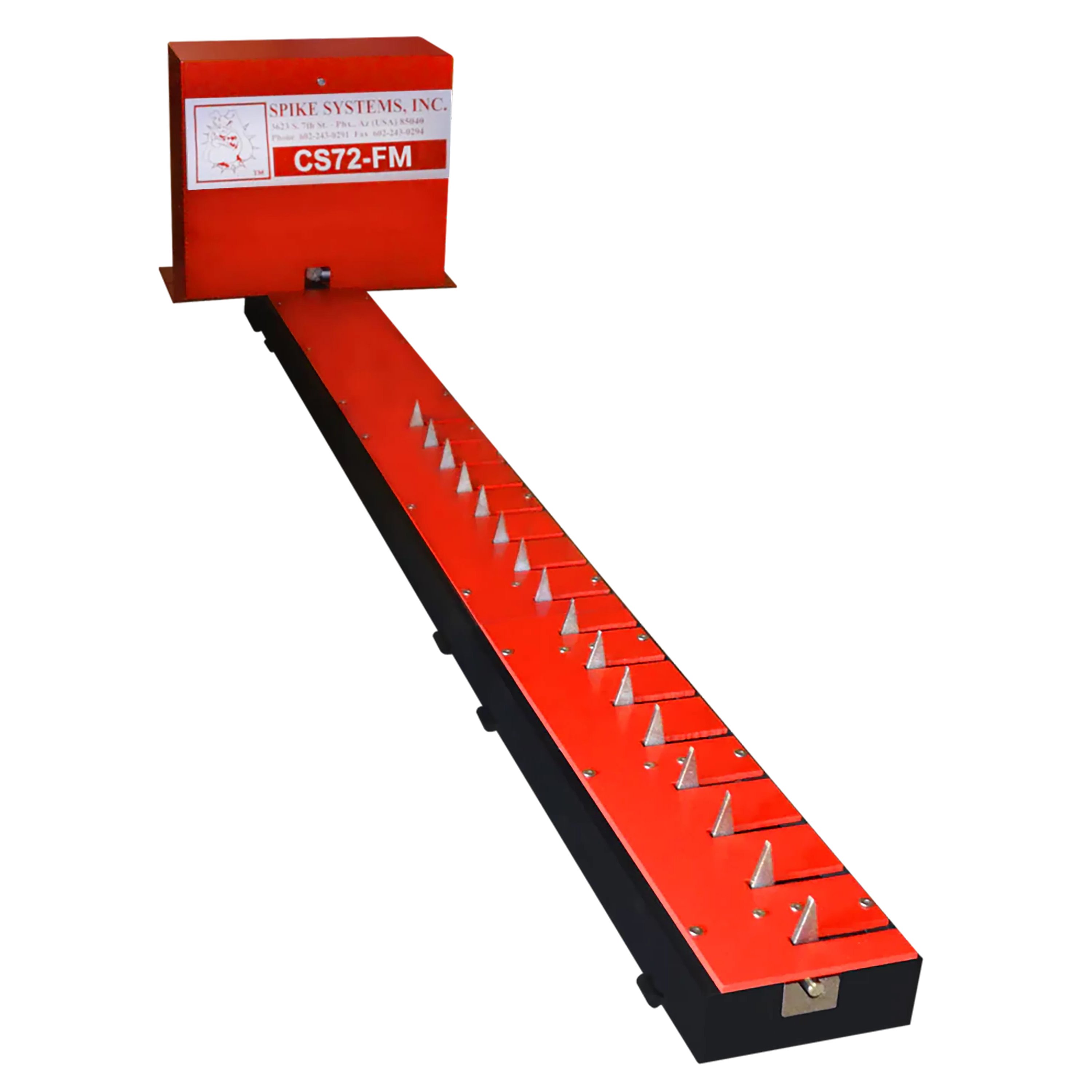
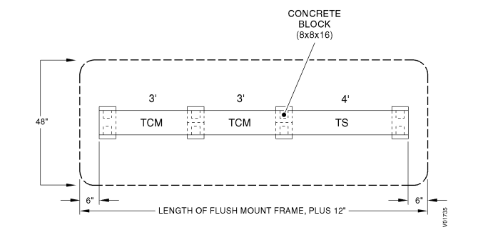
- Locate the Hydraulic Traffic Control System.
- Mark the Slotted Top Plate of the Traffic Control Module (TCM) that connects to the Tunnel Section. This Slotted Top Plate must be reinstalled in it’s original position.
- Remove the six outer bolts from the Slotted Top Plate on each TCM and remove the TCM’s from the flush-mount frame assembly.
- Remove the Top Plate from the Tunnel Section. Place a plastic bag or protective covering over the Hydraulic Actuator located in the Tunnel Section
- If necessary, attach any additional flush-mount frame sections to the main assembly with four bolts and four nuts.
- Excavate a trench approximately 48" x 13"deep. The trench length is dependent on the length of the flush-mount frame utilized in the system. Allow an additional 6 inches at each end of the flush-mount frame (see below) for clearance.
- Place a concrete block (8” x 8” x 16”) into the trench and position one at the end of each TCM and one at the end of the Tunnel Section
- Fill the center of each concrete block with pea gravel. This provides drainage when water enters the system. The top of the flush-mount frame should be approximately 1/2" to 3/4" above the pavement.
- Place the flush-mount frame assembly into the trench. Level the frame assembly on the concrete blocks and center it within the trench.
- Pour concrete to fill the trench to the top of the flush-mount frame. Do not let concrete enter the bottom of the flush-mount frame. Protect the hydraulic actuator during fill.
- Allow the concrete to set. Clean any excess concrete from inside the flush-mount frame assembly and remove the protective covering from the hydraulic actuator.
- Temporarily install the Tunnel Section top plate.
- Position the Hydraulic Control Unit at the end of the Tunnel Section. Allow a 1/8” gap between tunnel section top plate and the control unit box.
- Mark the location of the Hydraulic Control Unit mount holes on the concrete, remove the unit and install the 1/2” x 2 3/4” wedge anchor bolts. Refer to Appendix A for anchor bolt specifications and installation.
- Position the Hydraulic Control Unit over the anchor bolts and secure the unit to the concrete.
- Remove the Tunnel Section top plate.
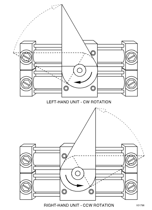
- Rotate the Hydraulic Actuator drive coupling to the spikes extended (up) position. This is different for left-hand or right-hand configuration systems
- With the spikes in the extended position, align the spike shaft drive coupling with the hydraulic actuator drive coupling and slide the TCM against the tunnel section as it is positoned on the flush-mount frame.
- Install the six outer bolts that secure the TCM to the flush-mount frame assembly. Do not tighten.
- Replace each additonal TCM on the flush-mount frame with the spikes extended and install the six outer bolts for each Slotted Top Plate. Do not tighten.
- Attach the hydraulic lines to the hydraulic actuator in the Tunnel Section. Red connector to Red line and Green connector to Green line.
- Run the hydraulic lines through the Tunnel Section and into the Hydraulic Control Unit.
- Tighten the outer bolts on the TCM’s.
- Connect the actuator limit switch wiring to the HCU
- Adjust the spike shaft travel
- Install the Tunnel Section top plate. Check for alignment or interference with the Hydraulic Control Unit box and secure with six bolts
- Locate the CS72-HTC-SM on a flat surface
- Slide the Tunnel Section to connect with the Hydraulic Control Unit and align the drive coupling with the Hydraulic Actuator
- Install two bolts and two nuts to secure the Tunnel Section to the Hydraulic Control Unit
- Slide the TCM to connect with the Tunnel Section and align the drive couplings
- Install two bolts and two nuts to secure the TCM to the Tunnel Section
- Slide the remaining TCMs together aligning the drive couplings
- Install the two bolts and two nuts to secure the TCMs together
- Install six achor bolts to secure each TCM and the Tunnel Section to the road surface
- Install the retaining nuts for the Hydraulic Control Unit
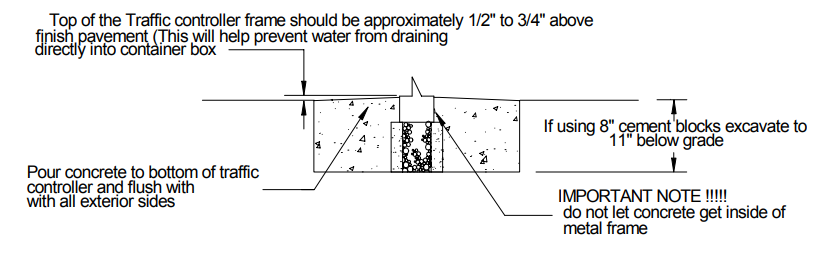
Care should be taken that NO CONCRETE IS PLACED INSIDE THE BOX FRAME ABOVE THE BOTTOM FLANGE. As this WILL (VOID) any warranties and damage the unit. Be sure that no cement is allowed to fall into the concrete block holes, these holes will be used for drainage.
Step Four: Finishing Installation
Printable Instructions
Spike Systems Motorized Traffic Spikes
Site Selection
Locate and accurately direct your pedestrian and vehicle traffic to ensure trouble-free operation of your Spike Systems Motorized Traffic Control System. Site selection is your first priority, and the following steps must be met to validate any warranty, implied or real:
For Flush-Mount Motorized Spike Systems:
For Flush-Mount Motorized Spike Systems:
Printable Instructions Shop All Traffic Spikes